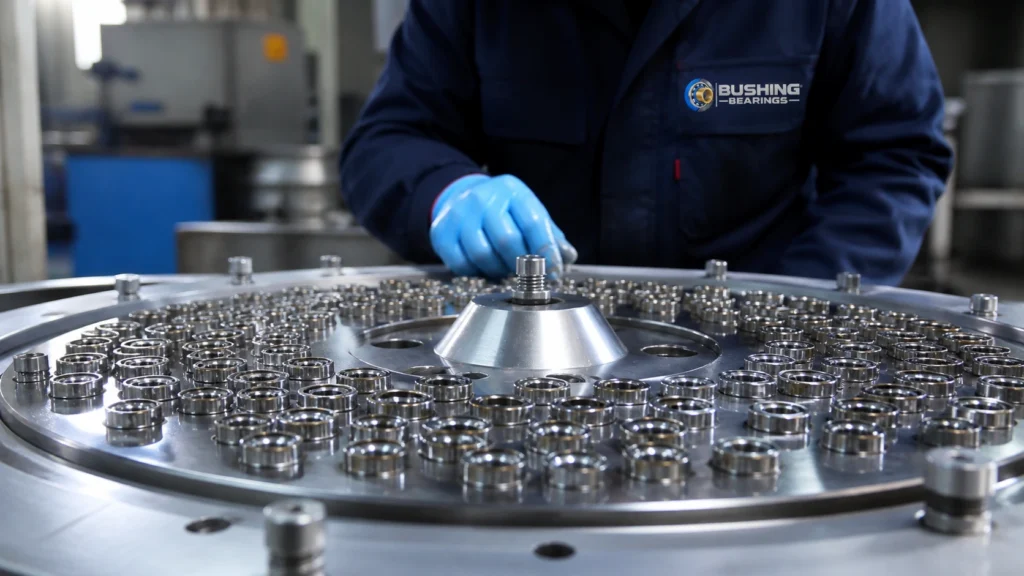
H2 Series Adapter Sleeves are used for clamping a tapered-bore bearing onto a plain shaft that has no machined bearing seat, and — in the withdrawal form — allowing it to be pushed off again in service. A slit tapered sleeve is drawn between the shaft and the tapered bearing bore by a lock nut, gripping the shaft as it expands and setting the bearing clearance as it goes. This page sets out the industries and machine positions where the type is specified, what has to be stated on the order, mounting practice, and the duties where a different bearing type is the correct answer. Boundary dimensions are to ISO 2982-1 / DIN 5415. This series is catalogued from 20 mm to 65 mm bore; the full table of boundary dimensions is further down the page.
Typical Applications for H2 Series Adapter Sleeves
The machine positions and sectors where this type is specified:
- Plain shafting: clamping a tapered-bore bearing onto drawn or turned shafting with no machined bearing seat.
- Plain shafting: clamping a tapered-bore bearing onto drawn or turned shafting that has no machined bearing seat anywhere along it.
- Plummer block lines: mounting spherical roller bearings in a line of pedestals on a long shaft.
- Conveyor drums and drive shafts: holding a self-aligning bearing at any chosen point on the shaft.
- Maintenance and rebuild: replacing a sleeve that rarely survives removal, together with the bearing it carried.
How to Specify H2 Series Adapter Sleeves for Your Application
- Bore: Start from the bore the shaft or housing gives you — this series is catalogued from 20 mm to 65 mm — then check the outer diameter and width against the space available. The boundary dimensions are fixed by the standard, so they are the same from any manufacturer; the load ratings and limiting speeds are not, and belong to the specific bearing being supplied.
- Sleeve, nut and washer: Order the sleeve with its lock nut and lock washer, and quote the bearing designation — the same shaft diameter is served by different sleeves depending on the bearing bore.
- Bearing bore and shaft range: A sleeve is specified by the tapered bearing bore it carries and the shaft diameter range it clamps — the same shaft size is served by different sleeves depending on the bearing. Quote the bearing designation on the order.
- Nut and washer: Order the matching lock nut and lock washer with the sleeve; the nut is the tool that produces the drive-up, not just a retainer, and the washer is single-use.
- Designation and suffixes: State the complete designation including every suffix. The base number gives the type and the boundary dimensions; the suffixes carry the sealing, the cage, the clearance group, the tolerance class and any special execution — and two bearings whose base numbers match but whose suffixes differ are not interchangeable.
- Clearance and tolerance: State the running clearance or fit class the assembly requires, together with the tolerances of the mating parts that produce it. For this type the clearance is created by the parts around the bearing rather than being built into it, which is precisely why it has to be written down.
- Sealing arrangement: This type is supplied open, so the sealing belongs to the housing around it. Specify the shaft seal, flinger or labyrinth that will keep the lubricant in and contamination out — with an open bearing, the sealing arrangement, not the bearing, decides how long it survives its environment.
- Cage: not applicable: This part has no cage and no rolling elements to separate, so the equivalent decision is the sliding material or liner. That is stated above, and it plays the same role: it is what sets the temperature limit and the lubrication requirement.
- Shaft and housing fit: Specify the seat tolerances, not just the bearing. The rule is that the ring which rotates relative to the load direction takes the interference fit: for a rotating inner ring under normal radial load the shaft seat is typically k5 or k6 with the housing bore H7, and where the outer ring rotates the interference moves to the housing (N7 or P7) with a clearance fit (g6) on the shaft. Heavier loads and hollow shafts move the fits tighter. A correctly chosen bearing in the wrong fit fails anyway — too loose and the ring creeps and frets its seat, too tight and the interference consumes the internal clearance and the bearing runs preloaded.
- Standard: Boundary dimensions are to ISO 2982-1 / DIN 5415. Quoting the standard on the order guarantees the mounting dimensions are interchangeable between suppliers — it does not standardize load ratings, limiting speeds or internal design, which remain manufacturer-specific.
Mounting & Assembly Practice
- Measure the radial internal clearance of the bearing with a feeler gauge before mounting, and again as the sleeve is driven up. The clearance reduction is the measurement that says the bearing is correctly mounted; the drive-up distance is a cross-check on it, not a substitute.
- Use a hook spanner or, above roughly 100 mm shaft diameter, a hydraulic nut. A sleeve of that size cannot be driven up accurately by hammer and drift.
- Fit a new lock washer with the nut, and bend a tab that actually lines up with a slot rather than forcing the nearest one.
- An adapter sleeve mounts from one side and a withdrawal sleeve from the other; check the direction against the arrangement drawing before assembly.
Common Selection Mistakes with H2 Series Adapter Sleeves
- Tightening the nut until it feels firm. Over-drive removes all internal clearance and the bearing runs preloaded from the moment it is started.
- Ordering by shaft diameter alone — the same shaft size is served by different sleeves depending on the bearing bore they carry.
- Reusing a sleeve that has been driven up hard: the slit sleeve is deformed by the clamping and does not grip the same way twice.
- Sizing this bearing from the boundary dimensions alone. Load ratings and limiting speeds are manufacturer-specific for this series and are deliberately not published here — take them from the catalog of the bearing actually being supplied and calculate the life against them.
Where H2 Series Adapter Sleeves Are Not the Right Choice
- A withdrawal sleeve is not an adapter sleeve: it is designed to be pushed out from under the bearing in service, and the two mount in opposite directions.
- A sleeve carries no bearing load itself and has no load rating — it grips the shaft, and the bearing on it does the work.
- Not for a shaft that already has a machined bearing seat, where a cylindrical-bore bearing fitted directly is simpler and more concentric.
- An adapter sleeve is not a withdrawal sleeve. They mount from opposite sides and are not interchangeable.
- Not for a duty where the bearing must be located axially by the sleeve; the sleeve grips by friction on the shaft and it will move under a sustained axial load.