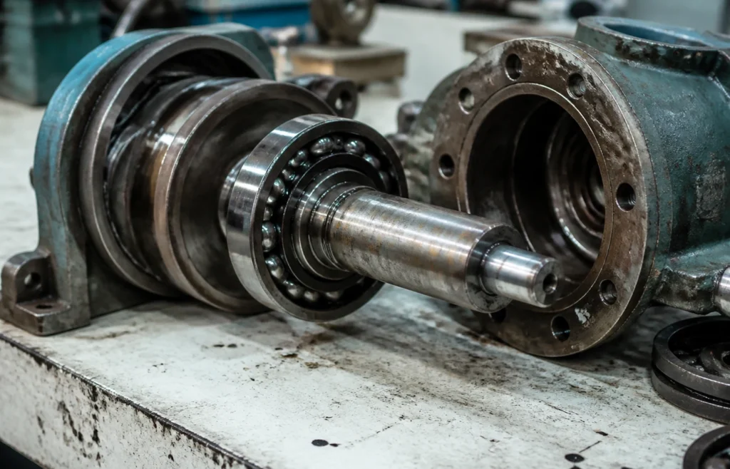
Application guide for 7200B Series Angular Contact Ball Bearings to ISO 15 / DIN 628-1 / GB/T 292. The core duty of the type is carrying combined radial and axial load where the axial component acts in one direction, mounted against a second bearing that takes it in the other. The line joining the ball contacts runs at an angle to the radial plane, so load is transmitted diagonally through the bearing: a single row can only push axially one way, and it must be opposed by something that pushes back. The typical industries, the specification checklist, mounting practice and the exclusion cases are set out below. This series is catalogued from 10 mm to 100 mm bore; the full table of boundary dimensions is further down the page.
Typical Applications for 7200B Series Angular Contact Ball Bearings
The machine positions and sectors where this type is specified:
- Machine tool spindles: matched sets carrying the cutting thrust and holding the spindle stiff, where preload sets the running accuracy and 15° angles are chosen for speed.
- Pumps: centrifugal impeller shafts, where the hydraulic thrust acts in one direction and the bearing that takes it is chosen for axial capacity.
- Worm and bevel gearboxes: shafts whose gear geometry generates a large, permanently one-directional axial force alongside the radial gear load.
- Vertical shafts: positions where the shaft weight itself is a permanent axial load with the radial load small.
- Compressors and blowers: axially loaded rotor shafts running at speed, arranged back-to-back for moment stiffness.
How to Specify 7200B Series Angular Contact Ball Bearings for Your Application
- Bore: Start from the bore the shaft or housing gives you — this series is catalogued from 10 mm to 100 mm — then check the outer diameter and width against the space available. The boundary dimensions are fixed by the standard, so they are the same from any manufacturer; the load ratings and limiting speeds are not, and belong to the specific bearing being supplied.
- Opposing bearing: Name the bearing this one works against on the order or the drawing. A single row is half of an arrangement, and the axial setting belongs to the pair, not to either bearing.
- Contact angle: The contact angle is the whole decision. A 15° bearing (7000 C) has the lowest axial capacity and the highest permissible speed; a 40° bearing (7000 B) takes far more axial load and runs slower. 25° and 30° sit between them. State the angle explicitly — it is a suffix, not an option, and two bearings with the same boundary dimensions and different angles are different bearings.
- Arrangement: Single rows are used in pairs and the pairing is part of the order. Back-to-back (DB) sets the load lines apart and gives a rigid, moment-carrying pair; face-to-face (DF) is more tolerant of misalignment and less stiff; tandem (DT) doubles capacity in one direction only and still needs opposing. Double row and four-point contact designs take both directions in a single bearing.
- Designation and suffixes: State the complete designation including every suffix. The base number gives the type and the boundary dimensions; the suffixes carry the sealing, the cage, the clearance group, the tolerance class and any special execution — and two bearings whose base numbers match but whose suffixes differ are not interchangeable.
- Preload class: This type is specified by preload rather than by an internal clearance group, because the axial setting is made when the bearings are clamped together on assembly. State the preload class (light, medium, heavy) on the order, and state the arrangement it applies to — the preload belongs to the set, not to one bearing.
- Seal or shield: State open, shielded (ZZ, 2Z) or sealed (2RS, 2RZ). A shield is non-contacting: it excludes coarse contamination and costs nothing in speed. A contact seal excludes fine dust and water and retains grease, but it rubs — it adds drag, raises the running temperature and lowers the permissible speed. Sealed bearings are also greased for life and cannot be relubricated.
- Cage material: State the cage. Pressed steel is the default and suits most duties; machined brass takes shock, high temperature and poor lubrication better and is used in large and heavily loaded bearings; polyamide is quiet, light and low-friction but has a temperature limit of about 120 °C and is attacked by aged oil. The cage is not a detail — it is the component that most often sets the real temperature limit of the bearing.
- Shaft and housing fit: Specify the seat tolerances, not just the bearing. The rule is that the ring which rotates relative to the load direction takes the interference fit: for a rotating inner ring under normal radial load the shaft seat is typically k5 or k6 with the housing bore H7, and where the outer ring rotates the interference moves to the housing (N7 or P7) with a clearance fit (g6) on the shaft. Heavier loads and hollow shafts move the fits tighter. A correctly chosen bearing in the wrong fit fails anyway — too loose and the ring creeps and frets its seat, too tight and the interference consumes the internal clearance and the bearing runs preloaded.
- Standard: Boundary dimensions are to ISO 15 / DIN 628-1 / GB/T 292. Quoting the standard on the order guarantees the mounting dimensions are interchangeable between suppliers — it does not standardize load ratings, limiting speeds or internal design, which remain manufacturer-specific.
Mounting & Assembly Practice
- Mount single rows in opposition and clamp both rings axially. A single angular contact bearing tightened on the shaft with the outer ring free is not located at all.
- A matched set is supplied ground so that clamping the rings together produces a defined preload. Keep the set together, keep the marks aligned, and do not substitute one bearing of a pair.
- Set the preload by clamping to the shoulders and locknut, not by force on a press. Rotate the shaft several turns while tightening so the balls take up their contact position before the final measurement.
- Do not swap the fit direction: the ring that is loaded in the axial direction takes the interference, and the opposing ring must remain free enough to be drawn up when the set is clamped.
Common Selection Mistakes with 7200B Series Angular Contact Ball Bearings
- Fitting one single-row angular contact bearing on its own and expecting the shaft to be located. It carries axial load one way and gives no location at all in the other; the shaft simply moves until something else stops it.
- Choosing a 40° bearing for its axial rating on a spindle running near the speed limit, when the whole reason a spindle uses 15° bearings is that the shallow angle lowers the centrifugal load on the ball and the heat it generates.
- Confusing DB and DF. They are not interchangeable: DB carries a tilting moment and DF barely does, and a DF pair fitted where a DB pair was designed leaves the shaft flexible enough to chatter.
- Sizing this bearing from the boundary dimensions alone. Load ratings and limiting speeds are manufacturer-specific for this series and are deliberately not published here — take them from the catalog of the bearing actually being supplied and calculate the life against them.
Where 7200B Series Angular Contact Ball Bearings Are Not the Right Choice
- A single row on its own gives no axial location in the second direction and cannot be used alone.
- Never on its own for a reversing axial load. A single row takes thrust in one direction only; reversing load unseats the contact and the balls skid across the raceway.
- Not where the axial load direction is unknown at design time — a double row or four-point contact bearing carries both directions in one part.
- Contact seals do not belong on precision spindle bearings: their drag is precisely the loss that a preloaded spindle bearing is specified to avoid.