9 catalogued sizes, dimensioned to ISO 2982-1 / DIN 5415. Pick any row and the technical drawing redraws to it.
H3 Series Adapter Sleeves to ISO 2982-1 / DIN 5415 are catalogued in shaft 20-60 mm, with bore 25-65 mm. 9 sizes are held in the table below, and the technical drawing redraws to whichever row you select.
Standard
ISO 2982-1 / DIN 5415
Shaft
20-60 mm
Bore
25-65 mm
Catalogued sizes
9
Dimensions are nominal values from the governing standard. Confirm the tolerance class for your application before ordering.
Technical Drawing
Customize the parameters below — every spec field is editable, and the drawing redraws to match the values you choose. Changing the designation snaps the other fields to that size's standard values; you can then override any individual value.
Sends the selected values to the quote form below.
Request a Quotation for H3 Series Adapter Sleeves
The form below follows the current technical drawing configuration. Change the drawing values above and the request details update automatically.
Dimensions & Specifications (ISO 2982-1 / DIN 5415)
Every row below is a starting point for the customizer above — pick any size and the drawing will redraw to that row.
Designation
Shaft diameter d (mm)
Bore d1 (mm)
Thread
Taper
For bearing series
H305
20
25
M25x1.5
1:12
1305 K, 2205 K
H306
25
30
M30x1.5
1:12
1306 K, 2206 K
H307
30
35
M35x1.5
1:12
1307 K, 2207 K, 22207 K
H308
35
40
M40x1.5
1:12
1308 K, 2208 K, 22208 K
H309
40
45
M45x1.5
1:12
1309 K, 2209 K, 22209 K
H310
45
50
M50x1.5
1:12
1310 K, 2210 K, 22210 K
H311
50
55
M55x2
1:12
1311 K, 2211 K, 22211 K
H312
55
60
M60x2
1:12
1312 K, 2212 K, 22212 K
H313
60
65
M65x2
1:12
1313 K, 2213 K, 22213 K
H3 Series Adapter Sleeves are bearing accessories manufactured to ISO 2982-1 / DIN 5415. This page carries the complete boundary-dimension table — bore, outer diameter, width and corner radius for every designation in the series — with the materials, mounting and selection notes that go with it.
What Are H3 Series Adapter Sleeves?
H3 Series Adapter Sleeves are bearing accessories defined by ISO 2982-1 / DIN 5415. They are selected by bearing designation and the dimensional characteristics shown below. Material, cage and sealing are specified separately from the designation and are covered further down this page.
Materials & Cage
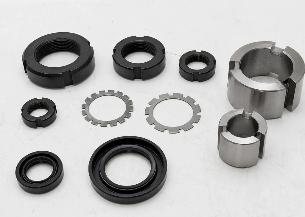
Lock nuts and lock washers are carbon or stainless steel; adapter and withdrawal sleeves are mild steel, slotted and threaded to draw a tapered bore onto a plain shaft; shaft seals are nitrile as standard, FKM for temperature and chemical service, PTFE where neither will run. Match the accessory to the bearing series it locates, not to the shaft diameter alone.
H3 Series Adapter Sleeves are supplied to order. Pricing starts from approximately US$4.50 per piece for standard sizes in the standard material for the series; final pricing depends on size, material, finish and order quantity (MOQ applies). Submit your exact configuration with the quote form above.
Specifying the H3 Series Adapter Sleeves
Most enquiries start from a shaft diameter rather than from a designation. The bore pages take one size at a time — 35 mm bore, 40 mm bore, 45 mm bore and 50 mm bore — and carry the boundary dimensions for that bore together with the shaft and housing tolerances that go with it.
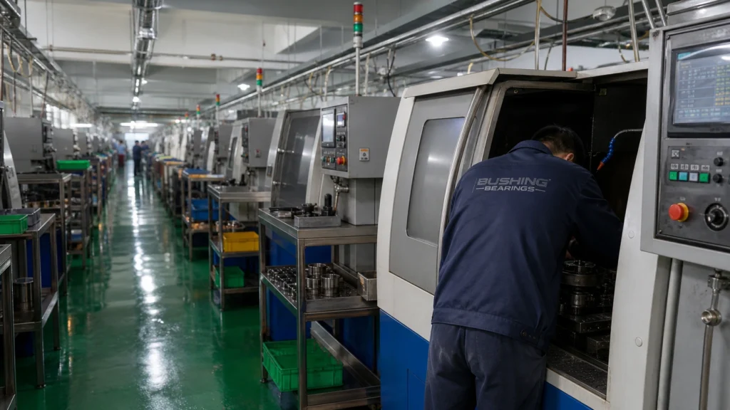
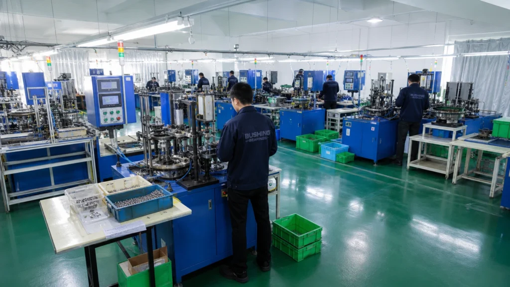
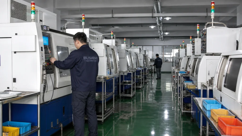
This bearing is forged, hardened, ground, superfinished and clearance-set in-house. The stages below are where its tolerance class, its internal clearance and its noise grade are actually decided.
01
Forging & turning
GCr15 bar and tube is cut, heated and forged into ring blanks, then turned to leave a uniform grinding allowance. Forging rather than machining from solid keeps the grain flow following the raceway, which is the surface that eventually fails.
Blank dimensions and grinding stock checked at set-up and per shift.
02
Heat treatment
Through-hardening brings GCr15 / 100Cr6 to 58–64 HRC; carburizing case-hardens 20CrMnTi where the section is heavy or the load is shock. Rings are then stabilized so they hold size in service rather than growing in the housing.
Core and surface hardness per lot; retained austenite and dimensional stability to the ordered temperature class.
03
Raceway grinding
Faces, bore, outer diameter and raceway are ground in sequence on separate machines. This is where the tolerance class is created: P0, P6, P5 or P4 is a grinding outcome, not a sorting outcome.
Bore and outer diameter deviation, raceway roundness and face runout measured to ISO 492 on every setup.
04
Honing & superfinishing
The ground raceway is honed to remove the grinding lay and bring surface roughness down to a fraction of a micrometre. Raceway finish is what decides whether a lubricant film forms, and therefore what decides bearing life far more than the load rating alone.
Surface roughness Ra and waviness measured per lot.
Third-party video, selected automatically for this topic. It is not produced by Bushing Bearings and is not a specification source — use the tables on this page for dimensional data.
Frequently Asked Questions
What standard governs H3 Series Adapter Sleeves, and how are they mounted?
H3 Series Adapter Sleeves are manufactured to ISO 2982-1 / DIN 5415, which fixes the boundary dimensions on this page. They are mounted with a slotted tapered sleeve drawn up by a lock nut, which clamps a tapered-bore bearing onto a plain shaft.
What is the size range of H3 Series Adapter Sleeves?
The table on this page lists 9 sizes for H3 Series Adapter Sleeves, ranging from H305 to H313. Sizes outside the table can be quoted on request.
In which materials are H3 Series Adapter Sleeves supplied?
H3 Series Adapter Sleeves are supplied in carbon and stainless steel for lock nuts, washers and sleeves; nitrile, FKM or PTFE for shaft seals. Material is only part of the specification: state the internal clearance group (or preload class), the seal or shield type and the cage material alongside the designation, because all three change the part you receive.
What shaft and housing tolerances suit H3 Series Adapter Sleeves?
The smallest bore on this page is 25 mm. With a rotating inner ring under normal load the shaft is normally machined to k5 or m6 and the housing to H7 or J7, so the inner ring is an interference fit and the outer ring can move axially to take up thermal growth. Reverse the fits when it is the outer ring that rotates. Check the figure against your own load case before machining.
How do I request a quotation?
Use the parametric drawing on this page to set the exact configuration — designation, internal clearance, seal type and cage — and click "Request this configuration". A specialist from Bushing Bearings will respond within one business day.
Need a bearing quote or a spec sheet?Message our engineers on WhatsApp — send a drawing or DIN number and get pricing back fast.Start WhatsApp Chat →
This website uses only necessary and functional cookies to operate, secure, and improve basic website performance.
We do not use advertising cookies, Google Analytics, or cross-site tracking technologies.