Skip to content
info@bushingbearings.com +86 15999653684

Cylindrical Roller Bearings · ISO 15 / DIN 5412-1 / GB/T 283 · Application guide

What Are N200 Series Cylindrical Roller Bearings Used For?

Typical applications, the industries that specify n200 series cylindrical roller bearings in 20 mm to 110 mm bore, how to state the designation, clearance, sealing, cage and fit on an order, and where a different bearing type is the right answer.

N200 Series Cylindrical Roller Bearings are used for carrying the highest radial load available in a given envelope, on line contact between roller and raceway, and — in the ribless designs — letting the shaft expand axially inside the bearing itself. Boundary dimensions are to ISO 15 / DIN 5412-1 / GB/T 283, and selection is driven by the radial load at the envelope available, and then entirely by the rib arrangement, which decides whether the position is located in one direction, both, or neither.

Primary duty
Carrying the highest radial load available in a given envelope, on line contact between roller and raceway, and — in the ribless designs — letting the shaft expand axially inside the bearing itself
Load direction
Radial only, unless the rib arrangement provides axial location
Bore range
20 mm to 110 mm
Boundary dimensions
ISO 15 / DIN 5412-1 / GB/T 283
Category
Cylindrical Roller Bearings

Application notes are general engineering guidance. Basic load ratings, limiting speeds and permissible misalignment vary between manufacturers for the same designation — verify them against the catalog of the bearing actually being supplied, and against your own bearing life calculation.

Gearbox spherical roller bearing — a typical application for N200 Series Cylindrical Roller Bearings
A typical service position for N200 Series Cylindrical Roller Bearings.

N200 Series Cylindrical Roller Bearings are selected when a machine position requires carrying the highest radial load available in a given envelope, on line contact between roller and raceway, and — in the ribless designs — letting the shaft expand axially inside the bearing itself. The roller contacts the raceway along a line rather than at a point, which spreads the load over a far larger area than a ball can, and the ribs — not the series number — decide what the bearing does axially. This application guide to the ISO 15 / DIN 5412-1 / GB/T 283 type covers concrete end uses, the specification checklist, mounting practice, and where an alternative bearing performs better. This series is catalogued from 20 mm to 110 mm bore; the full table of boundary dimensions is further down the page.

Typical Applications for N200 Series Cylindrical Roller Bearings

The machine positions and sectors where this type is specified:

  • Traction motors: the armature positions on rail traction, where radial load is heavy, shock is constant and the rotor must be free to grow axially.
  • Rolling mills and metals plant: roll necks and drive positions carrying loads that no ball bearing of the same envelope could approach.
  • Gearbox floating positions: the non-locating end of a shaft, where a ribless bearing absorbs thermal expansion inside itself and puts no axial force into either bearing.
  • Large electric motors and generators: the drive-end position of machines where the shaft grows several tenths of a millimetre as the winding heats.
  • Crushers, mills and vibrating plant: heavily loaded, slow to medium speed positions where full complement types add capacity in the same space.

How to Specify N200 Series Cylindrical Roller Bearings for Your Application

  • Bore: Start from the bore the shaft or housing gives you — this series is catalogued from 20 mm to 110 mm — then check the outer diameter and width against the space available. The boundary dimensions are fixed by the standard, so they are the same from any manufacturer; the load ratings and limiting speeds are not, and belong to the specific bearing being supplied.
  • Ribless outer ring: N has the ribless ring on the outside, which suits a housing that must be free of ribs, and is otherwise a floating bearing exactly like NU.
  • Rib arrangement: This is the type letter and it is not cosmetic: NU and N have a ribless ring, carry no axial load at all and float; NJ has one rib and locates the shaft in one direction; NUP and NF locate in both. NU204, NJ204, NUP204, N204 and NF204 are all 20 × 47 × 14 mm, so the dimension series answers the load question and the type letter answers the location question. State both.
  • Located and floating pair: Specify the pair, not the bearing. One position locates the shaft axially and one must be free; two located bearings on a shaft that grows when it warms will load each other axially until something yields.
  • Designation and suffixes: State the complete designation including every suffix. The base number gives the type and the boundary dimensions; the suffixes carry the sealing, the cage, the clearance group, the tolerance class and any special execution — and two bearings whose base numbers match but whose suffixes differ are not interchangeable.
  • Internal clearance group: State the radial internal clearance: C2 (reduced), CN (normal, and unmarked), C3, C4 or C5. Clearance is consumed after the bearing is fitted — by the interference fit on the shaft, and by the inner ring running hotter than the outer — so a bearing with a tight fit or a hot inner ring is ordered C3 and a bearing mounted lightly at even temperature is left CN. This field is left off orders more often than any other, and the bearing then arrives in the normal group by default.
  • Sealing arrangement: This type is supplied open, so the sealing belongs to the housing around it. Specify the shaft seal, flinger or labyrinth that will keep the lubricant in and contamination out — with an open bearing, the sealing arrangement, not the bearing, decides how long it survives its environment.
  • Cage material: State the cage. Pressed steel is the default and suits most duties; machined brass takes shock, high temperature and poor lubrication better and is used in large and heavily loaded bearings; polyamide is quiet, light and low-friction but has a temperature limit of about 120 °C and is attacked by aged oil. The cage is not a detail — it is the component that most often sets the real temperature limit of the bearing.
  • Shaft and housing fit: Specify the seat tolerances, not just the bearing. The rule is that the ring which rotates relative to the load direction takes the interference fit: for a rotating inner ring under normal radial load the shaft seat is typically k5 or k6 with the housing bore H7, and where the outer ring rotates the interference moves to the housing (N7 or P7) with a clearance fit (g6) on the shaft. Heavier loads and hollow shafts move the fits tighter. A correctly chosen bearing in the wrong fit fails anyway — too loose and the ring creeps and frets its seat, too tight and the interference consumes the internal clearance and the bearing runs preloaded.
  • Standard: Boundary dimensions are to ISO 15 / DIN 5412-1 / GB/T 283. Quoting the standard on the order guarantees the mounting dimensions are interchangeable between suppliers — it does not standardize load ratings, limiting speeds or internal design, which remain manufacturer-specific.

Mounting & Assembly Practice

  • These bearings are separable, which is why both rings can carry an interference fit at once: fit the ribless ring in the housing and the roller-and-cage assembly on the shaft, then bring the two together.
  • Introduce the roller set into the ribless ring squarely and slowly, with the rings concentric. Cocking the roller set on entry scores an axial line across the raceway, and that mark is a fatigue origin from the first revolution.
  • A mounting sleeve with a lead chamfer makes that entry repeatable; assembling by feel with the shaft hanging is what produces scored raceways.
  • Because both rings are usually a tight fit and the inner ring runs hot, C3 clearance is normal in this family rather than exceptional.

Common Selection Mistakes with N200 Series Cylindrical Roller Bearings

  • Ordering NU where the position has to locate the shaft. It carries no axial load whatsoever, so the shaft is unlocated in both directions.
  • Using NJ at both ends of a shaft facing the same way, which locates the shaft in one direction twice and in the other not at all.
  • Assuming a full complement version is a free upgrade. Removing the cage adds rollers and radial capacity, but rollers then rub against each other instead of being separated, and the limiting speed falls sharply.
  • Sizing this bearing from the boundary dimensions alone. Load ratings and limiting speeds are manufacturer-specific for this series and are deliberately not published here — take them from the catalog of the bearing actually being supplied and calculate the life against them.

Where N200 Series Cylindrical Roller Bearings Are Not the Right Choice

  • No axial capacity at all — the same exclusion as NU.
  • A cylindrical roller bearing will not tolerate misalignment. The roller contacts the raceway on a line, so a fraction of a degree of tilt moves the entire load onto the roller end, and the stress concentration there is what fails the bearing — use a spherical roller bearing where the seats cannot be held parallel.
  • No axial capacity in the NU and N types, at all. Any thrust in the assembly has to be carried by another bearing.
  • Full complement (SL, NCF) types have no cage, so roller-to-roller sliding contact sets a much lower limiting speed. They belong in slow, heavily loaded positions, not in a motor.
  • No axial capacity: the shaft has to be located by another bearing, a shoulder or a retaining ring.
  • This type will not tolerate misalignment. The rolling or sliding contact is a line, so a fraction of a degree of tilt moves the whole load onto the end of the contact and the stress concentration there is what fails the bearing.
Wind turbine gearbox bearing — a typical application for N200 Series Cylindrical Roller Bearings
Another position where N200 Series Cylindrical Roller Bearings are specified.

Technical Drawing

Customize the parameters below — every spec field is editable, and the drawing redraws to match the values you choose. Changing the designation snaps the other fields to that size's standard values; you can then override any individual value.

Sends the selected values to the quote form below.

Request a Quote

The form below follows the current technical drawing configuration. Change the drawing values above and the request details update automatically.

Request a Quotation

Specification
Business Information
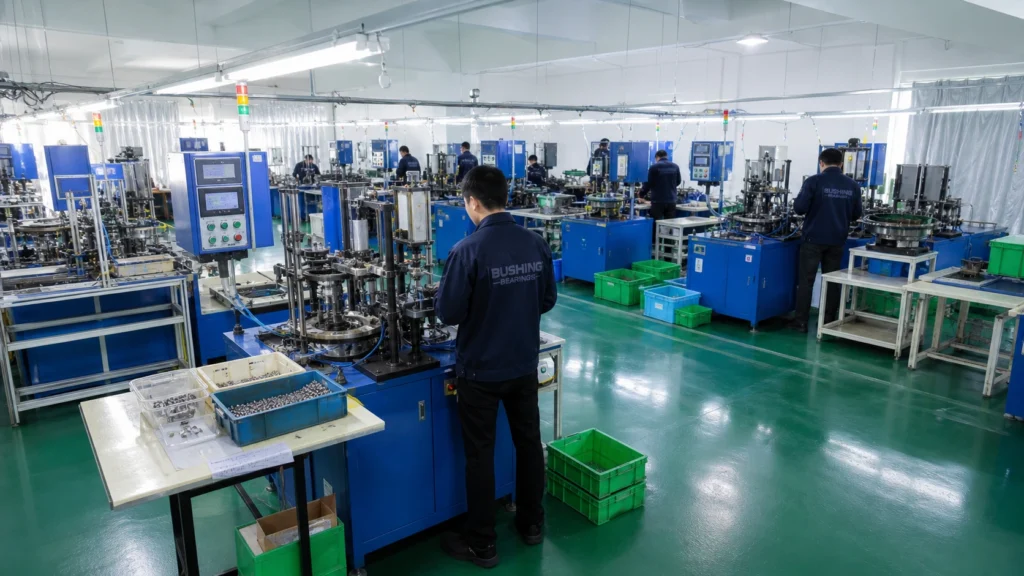
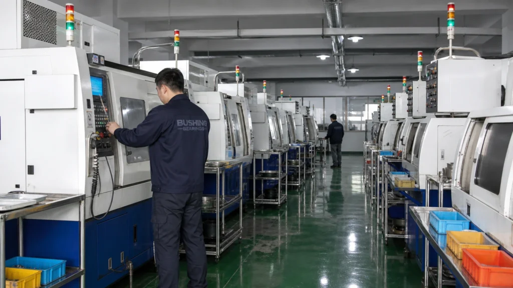
Our facility

Who makes the bearing behind this application

These are not resold from stock. Rings are forged and hardened here, raceways ground and superfinished here, and clearance set against the group you order — which is what makes a run repeatable a year later.

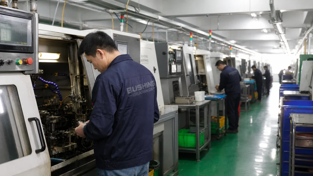
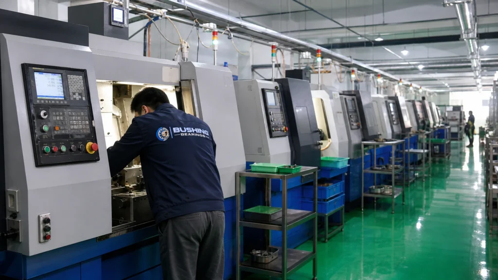
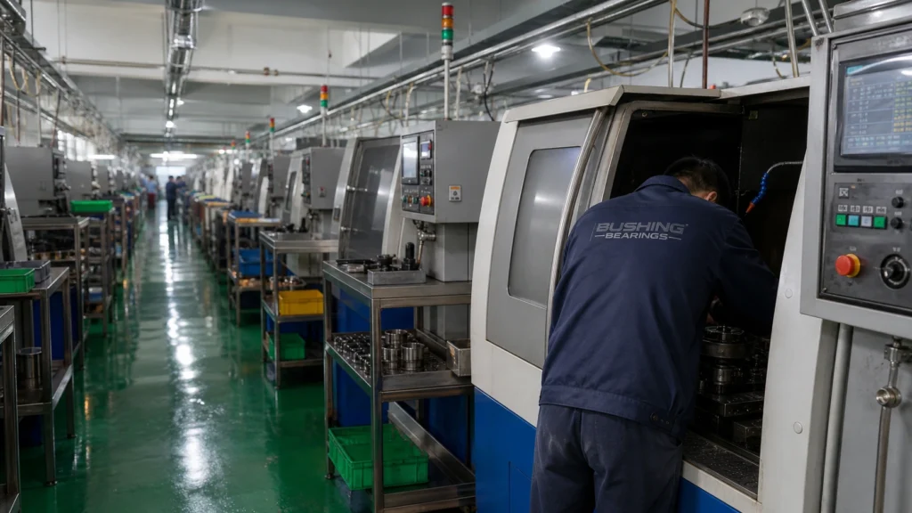
Bearing production line, wide view
Ring inspection station
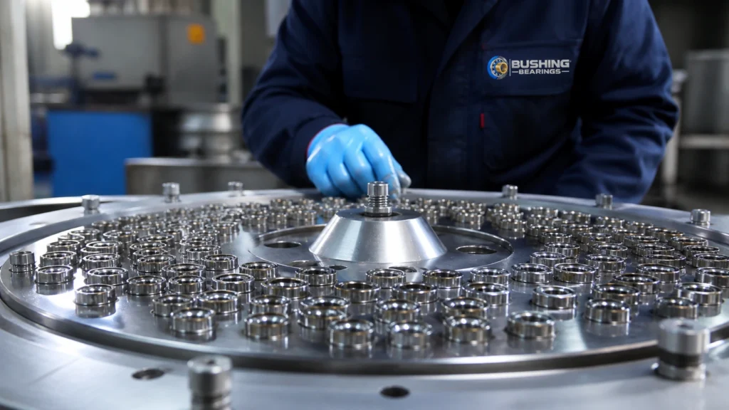
Bearing assembly and clearance setting
Finished bearings staged for packing

Dimensions & Specifications (ISO 15 / DIN 5412-1 / GB/T 283)

DesignationBore d (mm)Outer diameter D (mm)Width B (mm)Chamfer r min (mm)Rib arrangement
N2042047141Ribless outer ring, free at both ends
N2052552151Ribless outer ring, free at both ends
N2063062161Ribless outer ring, free at both ends
N2073572171.1Ribless outer ring, free at both ends
N2084080181.1Ribless outer ring, free at both ends
N2094585191.1Ribless outer ring, free at both ends
N2105090201.1Ribless outer ring, free at both ends
N21155100211.5Ribless outer ring, free at both ends
N21260110221.5Ribless outer ring, free at both ends
N21365120231.5Ribless outer ring, free at both ends
N21470125241.5Ribless outer ring, free at both ends
N21575130251.5Ribless outer ring, free at both ends
N21680140262Ribless outer ring, free at both ends
N21785150282Ribless outer ring, free at both ends
N21890160302Ribless outer ring, free at both ends
N21995170322.1Ribless outer ring, free at both ends
N220100180342.1Ribless outer ring, free at both ends
N221105190362.1Ribless outer ring, free at both ends
N222110200382.1Ribless outer ring, free at both ends

Video: What Are N200 Series Cylindrical Roller Bearings Used For? in use

Cylindrical Roller Bearings Explained | Types & Applications

Third-party video, selected automatically for this topic. It is not produced by Bushing Bearings and is not a specification source — use the tables on this page for dimensional data.

Inside the plant

Manufactured in our own plant

This bearing is forged, hardened, ground, superfinished and clearance-set in-house. The stages below are where its tolerance class, its internal clearance and its noise grade are actually decided.

  1. Bearing ring blanks coming off the forging press
    01

    Forging & turning

    GCr15 bar and tube is cut, heated and forged into ring blanks, then turned to leave a uniform grinding allowance. Forging rather than machining from solid keeps the grain flow following the raceway, which is the surface that eventually fails.

    Blank dimensions and grinding stock checked at set-up and per shift.

  2. Bearing rings entering a continuous hardening furnace
    02

    Heat treatment

    Through-hardening brings GCr15 / 100Cr6 to 58–64 HRC; carburizing case-hardens 20CrMnTi where the section is heavy or the load is shock. Rings are then stabilized so they hold size in service rather than growing in the housing.

    Core and surface hardness per lot; retained austenite and dimensional stability to the ordered temperature class.

  3. Raceway grinding machine finishing a bearing inner ring
    03

    Raceway grinding

    Faces, bore, outer diameter and raceway are ground in sequence on separate machines. This is where the tolerance class is created: P0, P6, P5 or P4 is a grinding outcome, not a sorting outcome.

    Bore and outer diameter deviation, raceway roundness and face runout measured to ISO 492 on every setup.

  4. Superfinishing stones acting on a ground raceway
    04

    Honing & superfinishing

    The ground raceway is honed to remove the grinding lay and bring surface roughness down to a fraction of a micrometre. Raceway finish is what decides whether a lubricant film forms, and therefore what decides bearing life far more than the load rating alone.

    Surface roughness Ra and waviness measured per lot.

Frequently Asked Questions

What is the difference between NU, NJ, NUP and N?

Only the ribs. NU has two ribs on the inner ring and a ribless outer: free at both ends, no axial location. N has the ribs on the inner ring and a ribless outer ring in the other arrangement, also free. NJ adds one rib and locates the shaft in one direction. NUP adds a loose rib ring and locates it in both. The boundary dimensions of all of them are identical for the same size.

Can a cylindrical roller bearing carry axial load?

Only if its ribs provide a path for it. NU and N types carry none. NJ carries a light axial load in one direction and NUP in both, but in every case that capacity is a fraction of the radial rating and it is limited by sliding friction and heat at the roller end face, not by fatigue.

Why are these used at the floating end of a shaft?

Because a ribless type accommodates axial movement inside itself: the roller set slides along the ribless raceway as the shaft grows with temperature. Both rings can therefore be fitted tightly, which is not possible with a bearing that has to slide in its housing to allow the same movement.

How do I choose the right size of N200 Series Cylindrical Roller Bearings?

Start from the bore the shaft or housing gives you — this series is catalogued from 20 mm to 110 mm — then check the outer diameter and the width against the space available, and confirm the calculated life against the load and speed. The full table of boundary dimensions is on this page.

Can I get a quote for N200 Series Cylindrical Roller Bearings in the size and specification I need?

Yes. Use the technical drawing and quote form on this page to set the size and options, then send the exact configuration — designation, clearance, sealing and cage — to our team for pricing and lead time.